Install Fuel Level Sensor
100339-00
Use the following task to install the Fuel Level Sensor.
Applicable Aircraft Serial Numbers
00021+
Type of Maintenance
Line
Level of Certification
LSA-RM
Task Specific Training Required
No
Special Tools Required
None
Parts Required
ICA011319 (PROBE, FUEL LEVEL SENSOR)
ICA012903 (GASKET, FUEL SENSOR)
ICA011512 (GASKET, ACCESS PLATE, FUEL TANK)
Aircraft System and Number
10—Instrument (and Avionics)
Safety Equipment
As Needed
Consumables
TT-I-735A or equivalent (ISOPROPYL ALCOHOL)
TY23MX (CABLE-TIE, NYLON 6-6, 18LB TY-RAP)
TY24MX (CABLE-TIE, NYLON 6-6, 30LB, 5.50, TY-RAP)
LOCTITE 423 (THREADLOCKER, PRIMERLESS, OIL TOL, REMOVABLE MED STR, BLUE)
ICA012861 (SEALANT, GASKET, FUEL RESISTANT)
Task Instructions
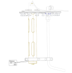
1. Install the new FUEL LEVEL SENSOR PROBE onto the Fuel Tank Access Plate:
a. Clean the Fuel Level Sensor Plate with ISOPROPYL ALCOHOL.
b. Orient Fuel Level Sensor Probe as shown in Figure 293 and install into the Fuel Access Plate using a new FUEL SENSOR GASKET, THREADLOCKER, 5X bolts, and 5x washers previously removed. Figure 292 Torque bolts in a star shaped pattern to 40-45 in-lbs.
Note:
The last bolt on the fuel level sensor will be installed at a later step.
d. Install Torx screw, nut, and 2x washers on the Clamp Bracket. While maintaining this position, torque Torx screws on Clamp Bracket to 7-10 in-lbs. (Figure 291)
Note:
Remove all 4 Torx screws if necessary for correct alignment.
Figure 293. Install CLAMP BRACKETS
2. Install the Fuel Level Sensor Assembly into the Fuel Tank:
a. Clean the Fuel Access Plate with ISOPROPYL ALCOHOL.
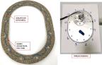
b. Apply SEALANT as one continuous bead approximately 0.030”-.060” thick to both sides of a new ACCESS PLATE GASKET.
Sealant to be applied as straight lines between bolt holes and half crescents to the interior around the bolt holes.
Allow Sealant to sit for 5 minutes after being applied to Access Plate Gasket surfaces before placing the Gasket onto the Fuel Tank.
c. Pull end of interior tubing from inside the Fuel Tank and secure to Fuel Level Sensor Assembly using 18lb CABLE-TIE. (Figure 290)
d. Lower the Fuel Level Sensor Assembly into the Fuel Tank ensuring that the Sealant only contacts the Fuel Tank Access Plate.
e. Secure the Fuel Tank Access Plate to the Fuel Tank using THREADLOCKER, 12 bolts and washers previously removed.
Torque bolts 25-30 in-lbs in a star shaped pattern as shown in Figure 294.
Repeat star shaped torque 2-3 times to ensure that gasket is evenly compressed and that all bolts are torqued to specification.
Figure 294. Fuel Tank Access Plate Gasket and Torque Sequence
a. Use a 7/16 wrench to install bolt, washer, and ring terminals T9028 and T9026 ring onto the Fuel Level Sensor Plate. Use THREADLOCKER and torque to 40-45 in-lbs.
b. Verify continuity to ground between ring terminals and ground stud.
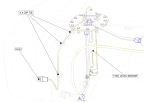
c. Secure the Fuel Level Sensor Harness and the T9028 ground wire to the Fuel Tank cable tie mount using three 30lb CABLE-TIEs. (Figure 295)
d. Connect the Fuel Level Sensor connector to D9039P on the Main Fuselage Wire Harness.
4. Connect Exterior Supply Line:
b. Connect the Exterior Supply Line to the Fitting on the Fuel Tank Access Plate. Torque to 110-130 in-lbs.
c. Apply THREADLOCKER and torque Coarse Fuel Filter clamp bolt to 25-30 in-lbs.
5. Perform a fuel calibration test to ensure the fuel level indicating system and low-level switch are operating correctly:
a. Sump fuel from the fuel tank.
b. Turn on aircraft to verify fuel low-level light comes on.
c. Add three gallons of fuel into the fuel tank—verify the low-level light goes out.
d. Add two more gallons of fuel into the fuel tank—verify fuel level sensor reads about 5 gallons.
6. Secure fuel level sensor wire harness to zip tie mounts on fuel tank using three zip ties.
Figure 295. Secure FUEL LEVEL SENSOR Wire Harness (T9028 Ground Wire Not Shown).
Verification Method
Step 5 acts as the verification method for this procedure.
Parent topic