Install Roll Cables
100364-00
Use the following task to install the upper and lower control cables.
Applicable Aircraft Serial Numbers
All
Type of Maintenance
Line
Level of Certification
LSA-RM
Task Specific Training Required
No
Special Tools Required
Flight Control Cable Tensiometer
3xDIA .185” Rig Pins
1xDIA .250” Rig Pins
Parts Required
2xICA008437 (CONTROL CABLE, ROLL, FUSELAGE)
2x ICA012104 (CLIP, LOCKING, TURNBUCKLE .042”)
2x MS21256-1 (CLIP, LOCKING, TURNUCKLE)
12x MS25665-151 (PIN, COTTER, CRES, .063” x .500”)
1x ICA005909 (CONTROL CABLE, ROLL, FUSELAGE, UPR)
2x-4x MS21043-3 (LOCKING NUT, 10-32)
Aircraft System and Number
06-Flight Controls
Safety Equipment
As Needed
Consumables
None
Install Lower Roll Cable:
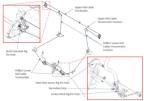
Figure 102. Fuselage Roll Control System
Task Instructions
2. Starting from the center wing loosely route new lower roll cable from the roll socket to the torque tube bearing. Use Figure 100 for routing path. (Figure 100)
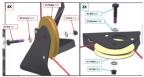
3. If the roll pullies were removed, reinstall the bolts and torque to 48 in-lb. If the safety pins were removed, re-install with a new MS25665-151 cotter pins. (Figure 103)
Figure 103. Roll Pulley Exploded Views
4. Connect the lower roll cable to the lower roll socket attachment point, with the bolts inserted from front to back, using new locking nuts(MS21043-3). Torque hardware to 20 in-lb.
5. Connect the roll cable to the rod end still attached to the cockpit control stick at the same time as connecting to the roll cable such that the threads are balanced. Do not fully tension the cable system during this step.
Note:
Ensure that when tightening the turnbuckle that the cable is held as to not wind the cable.
Install Upper Roll Cable
7. Temporarily separate the new upper roll cable by unthreading the turnbuckle that is connecting both ends.
Note:
When loosening the turnbuckle, ensure both ends of the cable are held to avoid winding and damaging the new cable.
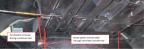
Route the upper control cable through the overhead console tray. (Figure 104) Careful not to damage any electrical wires while routing the cable. Snaking the cable is permissible.
Figure 104. Routing Upper Control Cable
9. Connect the upper control cable at the upper attachment point of the roll socket, with the bolts inserted from front to back, using new locking nuts (MS21043-3). Tighten hardware to 20 in-lb.
10. Re-connect the upper control cable at the turnbuckle. Do not fully tension the cables during this step.
Note:
When tightening the turnbuckle, ensure both ends of the cable are held to avoid winding and damaging the new cable.
Verification Method
The cables should be re-installed, and hardware torqued to the appropriate spec prior to rigging the system. Tensions should meet the requirements of the rigging section.
Parent topic