Propeller Pitch Check
100473-00
Use the following to check the propeller pitch.
Applicable Aircraft Serial Numbers
All
Type of Maintenance
Line
Level of Certification
LSA-RM
Task Specific Training Required
No
Special Tools Required
Tape Measure
ITL002081 (PITCH ADJUSTMENT TOOL)
Digital Protractor
Parts Required
None
Aircraft System and Number
13—Propulsion
Safety Equipment
As Needed
Consumables
Torque Stripe
Masking Tape
Note:
Measure from center of hub to center of the propeller blade.
Task Instructions
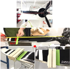
1. On all three blades, use tape measure to measure 25.5 inches outward from center of hub. Place a piece of masking tape on the blade with the outer edge of the tape at 25.5 inches to mark the location. (Figure 437)
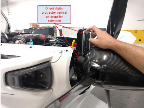
2. On one blade, place Pitch Adjustment Tool on blade with inner face aligned to the 25.5 inch mark. Figure 443
Figure 443. Position Pitch Adjustment Tool on Blade
3. Rotate one blade on the left side looking forward and make sure it is level with the ground and to the trailing edge of the wing. Figure 443
Note:
Perform the following steps as required until all 3 blade pitch angles are 19.2°-19.6° with attachment bolts tight. For optimal balance, all 3 pitch angles should differ from one another by no more than 0.1°.
Figure 444. Calibrate Digital Protractor
Note:
Do not bump the aircraft after calibration.
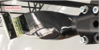
5. Carefully move the digital protractor and put the ditial protractor on the pitch adjustment tool in the same vertical orientation and measure angle of blade.Figure 445
Figure 445. Measure Angle of Blade
6. Continue to verify pitch angles of all blades through Step 4 and Step 5 and record the angles.
7. If the blade angle is not within the optimal pitch angles or differ from one another by more than 0.1°, contact ICON Aircraft for further support.
Verification Method
Perform Balance
Propeller.
Parent topic