Install Fuel Tank
100344-00
Use this procedure to install Fuel Tank Components.
Applicable Aircraft Serial Numbers
00021+
Type of Maintenance
Line
Level of Certification
LSA-RM
Task Specific Training Required
No
Special Tools Required
None
Parts Required
ICA010399 (TANK, FUEL, ROTOMOLDED)
CB9120V5 (MOUNT, CABLE TIE ANCHOR)
AN822-6-6D (FITTING, ELBOW, 3/8 FLARED TUBE & 3/8 NPT)
AN840-4D (COUPLING, BARB-PIPE THREAD, .250X.125NPT)
Aircraft System and Number
07—Fuel System
Safety Equipment
As Needed
Consumables
TT-I-735A or equivalent (ISOPROPYL ALCOHOL)
MA830 (ADHESIVE, METHACRYLATE, 2-PART, PLEXUS MA830)
LOCTITE 243 (THREADLOCKER, PRIMERLESS, OIL TOL, REMOVABLE MED STR, BLUE)
Task Instructions
1. Inspect the new FUEL TANK for any damage. Remove all FOD before assembly.
2. Bond a CABLE TIE ANCHOR MOUNT inside the Fuel Tank as follows:
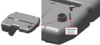
a. Mark the location of the CABLE TIE ANCHOR MOUNT as shown in Figure 158 in a similar orientation as the ITL tool.
b. Prep bonding surface by abrading with 80 grit sandpaper and cleaning with ISOPROPYL ALCOHOL.
c. Remove all FOD inside the Fuel Tank after prepping surface for bonding.
d. Bond CABLE TIE ANCHOR MOUNT with PLEXUS MA830
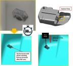
e. Set time is 30 minutes. Do not remove the plastic bonding fixture yet.
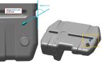
3. Bond the next 9 CABLE TIE ANCHOR MOUNTs as on the Fuel Tank as follows:
a. Mark the location and orientation of the CABLE TIE ANCHOR MOUNTs as shown in Figure 159-Figure 163.
b. Prep bonding surface by abrading with 80 grit sandpaper and cleaning with ISOPROPYL ALCOHOL.
c. Bond CABLE TIE ANCHOR MOUNTs with PLEXUS MA830.
d. Set time is 30 minutes. Remove the plastic bonding fixture after a minimum of 30 minutes has elapsed.
Figure 158. Cable Tie Anchor Mount Location Inside Fuel Tank
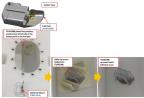
Figure 159. Cable Tie Anchor Mount Exterior Locations 1 & 2
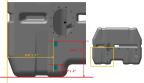
Figure 160. Cable Tie Anchor Mount Exterior Locations 3-5
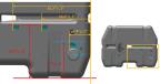
Figure 161. Cable Tie Anchor Mount Exterior Locations 6&7
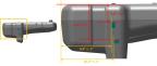
Figure 162. Cable Tie Anchor Mount Exterior Location 8.
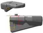
Figure 163. Cable Tie Anchor Mount Exterior Location 9.
4. Proof load test the Cable Tie Anchor Mount installed on the interior of the Fuel Tank after at least 30 minutes has elapsed. Figure 164
a. Remove the plastic bonding fixture.
b. Secure metal wire around Cable Tie Anchor Mount and end of force gauge.
c. Slowly, pull upwards on force gauge as perpendicular to bonded surface as possible until force of 10 ± 2.5 lbs. is applied.
d. If Cable Tie Anchor Mount bond fails (disbonds), disassemble and re-work the bond as required from Step 3. Re-check proof load test after cure times.
e. If proof load test passes, disconnect wire from Cable Tie Anchor Mount and remove FOD from inside the Fuel Tank.
Figure 164. Proof Load Test
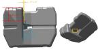
5. Install the 3/8 FLARED TUBE ELBOW FITTING into the Fuel Tank as shown in Figure 165 and as follows:
a. Apply THREADLOCKER as a 360° bead to the leading threads of the Elbow Fitting.
b. Install Elbow Fitting into fuel tank. Wrench tighten a minimum of 1/2 turns from finger tight, then continue tightening to orient fitting as shown, adding no more than 1 additional turn.
Figure 165. 3/8 Flared Tube Elbow Fitting Installation
CAUTION:
Do not exceed 200 in-lbs while torqueing and do not loosen to achieve alignment.
6. Apply THREADLOCKER as a 360° bead to the leading threads of BARB-PIPE THREAD COUPLING and install into fuel tank as shown in Figure 166. Wrench tighten 2-3 turns past finger light.
Figure 166. Barb-Pipe Thread Coupling Installation
7. Install the Low Fuel Level Sensor. (Install Low Fuel Level Sensor (00021-00109))(Install Low Fuel Level Sensor (00110+))
Verification Method
Complete the Engine Test Run and check for leaks. (Engine
Test Run)
Parent topic